Build the rack, part 2: mount, patch, power
The physical build of a 10-inch home lab: mounting order, the SFP+ card in a Tiny, patching per the port map, one supply per Pi, and the ISP router's settings.
 Mica Voss@micavoss7 min read
On this page
With the plan from part 1 printed and the parts on the bench, the physical build is an evening. The order below is the one that avoids taking things out again, and the two rules that matter are easy to state: patch exactly per the port map, and do not power anything on yet except the switch.
Before the frame: the two Tinys
The firewall Tiny gets its network card first, while it is still on the bench and not in a mount.
- Open the M920q, seat the two SO-DIMMs and the NVMe drive.
- Fit the PCIe riser into the Tiny’s slot and the Mellanox ConnectX-3 SFP+ card into the riser. The card shares its position with the 2.5-inch bay, so this Tiny has no 2.5-inch drive; it does not need one.
- Fit the printed rear baffle. The stock rear plate has no opening for a full-height SFP+ cage; the baffle closes the gap around the card and keeps the airflow through the chassis.
- Plug the DAC into the card now, label the switch end
FW TRUNK, and leave the cable hanging. Seating a DAC inside a rack is fiddlier than seating it on the bench.
The hypervisor Tiny only gets its memory, the NVMe and the 2.5-inch disk. Both go into the same printed mount:
Mounting order, bottom up
- Cage nuts and rails everywhere you will need them, including the units that stay empty for now. Adding a cage nut behind a mounted device later is the job everyone hates.
- The NAS carrier at the bottom (U1 to U5). Install the drives in the DXP4800 before it goes in, then slide it onto the carrier. If the frame is shallower than the NAS, this is where you find out: stand it on top of the cabinet and run one cable down instead.
- The PDU above it. Every power brick ends up behind the PDU, and the PDU’s own lead goes out the back to the wall.
- The two Tinys in their mounts: the firewall with the SFP+ card lower, the hypervisor above it. Rear to the back.
- The Pi shelves: the Pi 4B and the JetKVM on their shared mount, the two Pi 5 on the dual mount above. If the umbrelOS Pi gets an NVMe HAT and SSD, fit them before the Pi goes on the mount.
- The switch near the top on its own 10-inch ears, and the keystone patch panel above it.
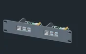
Rack height: 1U · Depth: 92 mm · Mounting: 3D-printed 1U dual-board carrier
Details & sources →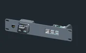
Rack height: 1U · Depth: 92 mm · Mounting: 3D-printed 1U combined carrier
Details & sources →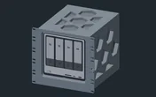
Rack height: 5U · Depth: 267 mm · Mounting: 3D-printed 5U NAS carrier
Details & sources →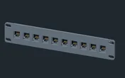
Rack height: 1U · Depth: 29.4 mm · Mounting: 3D-printed 1U carrier
Details & sources →Keep power on one side of the frame and data on the other. A 10-inch rack has no cable management to speak of, so the only thing standing between you and a nest is a rule you set before the first cable.
Patching per the port map
Patch one cable at a time against the port map, labelling both ends with the port number and the device. Three ports stay empty for now: port 1 (the ISP router, which waits until the switch is configured in part 3), port 5 (the spare NAS port) and port 8 (the emergency WAN, which is never patched in normal operation).
Count the ports before you plug. On the CSS318 the odd numbers are the top row and the even numbers the bottom row, with 1 and 2 at the left and 15 and 16 at the right next to the SFP+ cages. In this build the laptop, the Pi and the ISP router each landed one port off at first. The switch tells you where a cable really is: its Link tab shows which port has a link, and the port names from part 3 make the mistake obvious.
Colour helps more than labels at a glance: blue for the servers network, grey for the LAN, yellow for IoT, red for anything on the ISP side, green for management. When a red cable is in a port that should be green, you see it from across the room.
The JetKVM connects to the firewall Tiny with two cables of its own: HDMI (through a DisplayPort adapter if the Tiny’s rear module has no HDMI port) and USB-C to one of the Tiny’s rear USB-A ports. Its network cable goes to switch port 2.
One power supply per Pi
This is the lesson of the build, and the reason it has its own section. The three Pis were first powered from one USB hub that was itself bus-powered and that also charged phones. It ran for days. Then one evening every Pi dropped at once: the hub browned out, the DNS server went with it, and so did the watchdog that was supposed to report it.
The Pi 5 wants 5 V at 5 A from its own supply, the Pi 4B 5 V at 3 A. Give each one the official supply, or an equivalent that is rated for it, and keep chargers off anything the rack depends on. The Pi records whether it has ever been short of power since it booted:
vcgencmd get_throttled
0x0 means fine. 0x50000 means under-voltage happened since boot, even if everything looks healthy now. Check it after the first day; part 9 wires it into the monitoring so you do not have to remember.
The ISP router
The ISP router stays. It keeps its own firewall in front of OPNsense (double NAT, no DMZ), which costs nothing at home and gives a second wall should a firewall rule ever be wrong. Three settings on it are worth doing now, from the laptop plugged into one of its LAN ports:
- Shrink its DHCP pool to the upper half of its range, for example
.100to.199. Everything below is then free for the fixed addresses of the ISP side: the firewall’s WAN, the JetKVM and the watchdog Pi. - Reserve the firewall’s WAN address by the MAC of the SFP+ card, since the WAN rides the 10G trunk. Look at the lease table first; the pool can start right at
.2, and in this build.2was already taken by another device. - Keep its Wi-Fi on with a new strong password and a rescue name. That Wi-Fi is your way to the JetKVM when the firewall is down. Switch WPS off if the menu offers it. If the household’s phones and TVs are on this Wi-Fi today, leave its name as it is until the rack’s own access point takes over.
Leave port forwards off until something needs one, and when it does, forward only to the firewall’s WAN address, never to a device inside. Bridge mode (the firewall gets the public address directly) is not needed for any part of this series; double NAT works, and the DMZ option is the step in between if you ever want it.
Do not patch the router into switch port 1 yet. A half-configured switch can leak the router’s DHCP into other ports; the router goes in at the end of part 3.
Power-on order
Only the switch is powered now. The ISP router stays where it is. The Tinys, the NAS and the Pis wait for their parts: the switch first (part 3), then the hypervisor (part 6) and the firewall (part 4). The order in the series is the order in which each device can be reached from the service laptop without a working network behind it.
Checklist before part 3
- Every device in its unit, every brick behind the PDU, one supply per Pi.
- Every cable labelled at both ends and patched per the map, except ports 1, 5 and 8.
- The DAC seated at both ends: the firewall’s card and SFP+ cage 1 on the switch.
- The ISP router’s pool shrunk, the firewall’s WAN reserved, the rescue Wi-Fi set.
- The laptop on port 16 with a static address for the switch’s factory network (part 3 starts there).
Part 3 configures the switch: the VLAN table, the per-port behaviour, the snooping settings that keep multicast alive, and the management lockdown that comes last for a reason.
Sources
Related guides
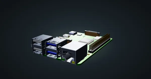
Raspberry Pi 4 Model B in a 10-inch rack
Racking the Raspberry Pi 4 Model B: three printable mounts including a 2-SSD NAS plate, a 5 V / 3 A USB-C supply and one front Gigabit port.
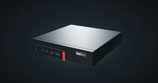
Lenovo ThinkCentre M710q Tiny in a 10-inch rack
How the ThinkCentre M710q Tiny fits a 10-inch rack: the M910q's budget sibling on B250, no vPro, no PCIe slot, a rear Gigabit port and two 1U mounts.
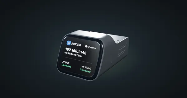
JetKVM in a 10-inch rack
JetKVM in a 10-inch rack: KVM-over-IP for the machine beside it, three printable combo mounts, a rear 100 Mbps port and a tiny power budget.